1.FIRST STEPS
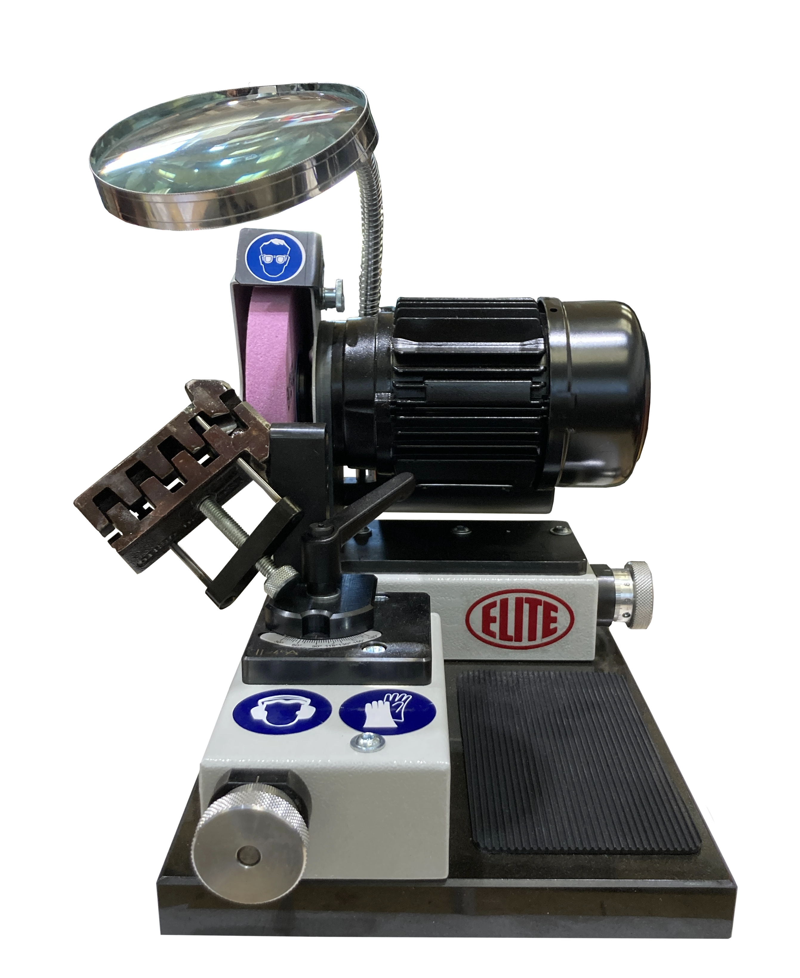
Congratulations on your purchase of the ELITE model B 20 drill and countersink sharpening machine.
Please read this guide before you begin.
The ELITE model B 20 is a drill and countersink sharpening machine. It can sharpen drill bits from ø1 to ø 20 mm
This manual introduces you to the main functions of the sharpening machine in order to avoid risks to your health or that may cause a breakdown or premature wear of the machine.
If you have any questions, please contact us directly or one of our authorized distributors
Informative Note: The use described in the manual for this sharpening machine may present some variations in use since our machinery is subject to possible construction modifications, depending on the incorporation of technological advances in our sharpening equipment.
2. SECURITY
2.1.Safety rules
Carefully observe and apply the following safety rules, non-observance of these rules may cause personal injury or damage to the machine itself.
The installation and maintenance of the machine described in this manual must be carried out only by operators who are familiar with its operation and have sufficient technical knowledge.
The ELITE model B 20 drill and countersink sharpening machine has been designed for sharpen drill bits from ø1 to ø 20 mm. excluding any other type of operation.
DANGER HIGH VOLTAGE

DANGER OF ACCIDENT

DANGER DUE TO SPARK PROJECTION

WEAR PROTECTIVE SHOES
DANGER FROM SHARP TOOLS

USE HEARING PROTECTORS
These warnings do not include all possible risks that could be caused by improper use of the machine. Therefore, the operator must proceed with prudence and observing the rules.
2.2.Use and preservation of the instruction manual
This instruction manual must be read and understood by all personnel who come into contact with the machine.
This guide is for:
- Indicate the correct use of the machine according to the type of work to be carried out.
- Provide the necessary instructions for the transport, adjustment and maintenance of the machine.
- Facilitate the order of spare parts and risk information.
Limits of use of the manual:
The machine is intended for professional use and therefore the experience of the operator is necessary and of vital importance.
Importance and conservation of the manual:
This manual must be considered an integral part of the machine and must therefore remain with it until the end of its use.
Additional information and clarifications:
The user, owner or maintenance person can contact the manufacturer to request any additional information on the use of the machine and the possible modalities of maintenance and repair intervention.
Expiration of responsibility:
The manufacturer is considered exempt from any responsibility in case of:
- Improper use of the machine
- Use of the machine by untrained persons
- Serious failures in scheduled maintenance
- Unauthorized interventions or modifications
- Use of non-original spare parts.
2.3.Declaration of conformity
The company hereby:
Elite Sharpening Machines, SLU
Joan Oró, 27
ES-08635 Sant Esteve Sesrovires
Declares that the product indicated below, based on its conception and construction, as well as the version put on the market by our company, complies with the mandatory basic health and safety requirements of the CE directive.
This declaration loses its validity in the event of unauthorized modifications to the product.
Product name: ELITE B 20
Product type: drill and countersink sharpening machine.
Serial number.: __
EC Directive Competences:
- EC Machinery Directive (2006/42/EC)
- European directive on electromagnetic compatibility (2014/30/EU)
- The protection purposes of the CE low voltage directive (2006/95/CE) were fulfilled according to annex I, nr. 1.5.1 of the machinery directive 2006/42/EC
The technical documentation was compiled by legal representative of the documentation:
Sergi Valls Gramunt
Joan Oró, 27
ES-08635 Sant Esteve Sesrovires
Date / manufacturer - Signature: __
Signatory data: Sergi Valls Gramunt, manager
3.TECHNICAL DATA
In the following table of information, find the list of technical specifications of the setter described in this manual.
| TECHNICAL DATA | ELITE B 20 |
|---|---|
| Sharpening capacity | From ø1 to ø20 mm (0.039" to 0.78") |
| Type of drills | 2-3 and 4 cuts drills for wood or steel, right and left |
| Travel range. Motorslide | 55 mm |
| Travel range. Prism feed | 45 mm |
| Clamping range prism | 2,0 - 20,0 mm |
| Connection voltage | 220 V. single phase |
| Noise emission | <70 dB (A) |
| Stopping time of grinding wheel | around 10 seconds |
| Machine dimensions | 290 x 220 x 250 mm |
| Weight net | 13,5 Kg |
4. TRANSPORTATION
The ELITE B 20 sharpening machine is delivered packed in a wooden box.
During all transport and transfer, the machine must be kept in its original vertical position, any variation in this position may result in the loss of the warranty.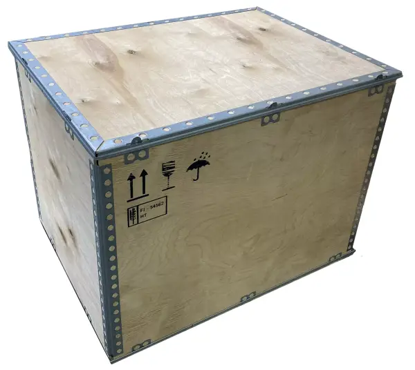
| AVAILABLE VERSIONS | ||
|---|---|---|
| Model | Packing Size | Gross weight |
| B 20 | 370 x 310 x 260 mm. | 32 Kg. |
4.1.Unpacking and assembly instructions
Tenga especial cuidado al levantar la carga: ¡La carga puede no estar centrada!
Para levantar o mover la carga, utilice una carretilla elevadora con palas lo suficientemente largas como para soportar la máquina, teniendo en cuenta el ancho y la profundidad de la máquina al calcular los pesos a levantar.
Para desembalar, retire el panel superior y las piezas de madera que puedan bloquearla.
Una vez que la máquina esté en su ubicación definitiva, puede retirar la película protectora y otras protecciones de los componentes que sujetan y evitan que la carga se mueva.
5.INSTALACIÓN
5.1.Positioning the machine
Before any work, make sure that the machine is properly aligned and does not oscillate at any of its ends, in which case it must be wedged to prevent movement. To ensure proper levelling, a levelling tool must be used. This check must be carried out both longitudinally and transversely.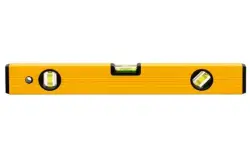
Poor levelling of the machine can cause unwanted vibrations and premature wear.
ATTENTION: The machine must not be used under any circumstances by unqualified or unauthorized personnel.
5.2. Electrical connection

HIGH VOLTAGE DANGER!
Remember: before connecting the machine, remove any protection that the machine may have to protect the components during transport.
The ELITE B 20 sharpener must be connected strictly to the voltage indicated on the machine order and on the machine itself. Connection to a voltage different from that indicated may cause a breakdown in the machine and represents a risk for people using the machine.
For connection to the mains, the machine requires 1 Ph.
This installation must be carried out by qualified technical personnel and checked with a voltage meter before turning on the machine.
It is absolutely essential that the section of the connection cable is the required one, that the machine has a dedicated socket protected against overloads and that it is as close as possible to the power outlet.
We decline any liability for incorrectly made connections.
Once the connection has been made and checked, turn the main ON/OFF switch to the ON position.
5.3.Main components of the machine

1.Grinding wheel cover, complete
2.Motor switch (left- or right- hand turn)
3.Motor 230 V 50 Hz single phase
4.Prism support with 2 boring for prism fixation
5.Knurled screw for prism fixation
6.Clampling lever for top angle adjustment
7.Slide for drill feed
8.Knurled nut with scale for motor feed
9.Knurled nut with scale for drill feed
10.Reversing prism, clamping range from 2-20mm
11.Special corundum grinidng wheel
12.Adjustable splash guard
13.Optical lens
5.4. Optional accessories
- 3 cuts drills adaptor
- Morse taper 1 short drills holder
- Morse taper 2 short drills holder
- Special corundum grinding wheel
- Diamond grinding wheel
- CBN Grinding wheel
6. START UP
In this section we show you how to operate the B20 to make it work.
NOTE: The data that appears in the different images are by way of example, each type of tool has its recommended data and an expert operator should know them.
DANGER: never manipulate the buttons on the control panel while performing maintenance on the machine: danger of very serious injury. It is strongly recommended to switch off and disconnect the machine from the mains when working inside it.

6.1. Power on the machine
After switching on, a warning light on the control panel lights up. This lamp indicates that the setup process can be started
6.1.2. Electrical connection
The ELITE B 20 sharpening machine must be strictly connected to the voltage indicated on the machine order and on the machine itself. Connection to a voltage other than that indicated may cause a breakdown of the machine and represents a risk to the people using it.
This installation must be carried out by qualified technical personnel and verified with a voltmeter before switching on the machine.
It is absolutely essential that the section of the connection cable is the required one, that the machine has a specific power socket and is protected against overloads and shunts, and that it is as close as possible to the power socket.
We reject any responsibility for a bad connection.
Once the connection has been made and checked, turn the main ON / OFF switch to the ON position.
ELITE Sharpening Machines declines all responsibility for a bad connection, which in addition to causing a malfunction of the machine can harm people, animals or objects.
7. OPERATION OF THE WORK
7.1.Mounting and dressing of the grinding wheel before the first operation
After you have moved the machine to its final place of working, take the wheel and make a sound check as well as optical control of damage. Mount together the grinding wheel with its support
After you have mounted the grinding wheel support, place the wheel on the motor spindle (see section 7.3).
After the grinding wheel is placed correctly on the motor spindle and the grinding wheel cover is mounted, start dressing the grinding wheel first (see section 7.2).
Only after observing these steps, a save and correct operation is possible!
7.2.Dressing of the grinding wheel
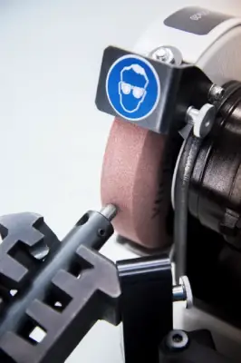
For dressing of the grinding wheel, please release the clamping lever and place the prism rest on the 150º graduation line.
Fix the diamond dresser device in the prism and fix the prism with the knurled fixation screw in the bottom boring hole of the prism rest.
Move the motor feed with the knurled nut slowly towards the turning grinding wheel. When the diamond pin touches the grinding wheel, then move the motor feed back and forth. Do not feed more than 1-2 scale graduations. For sheet metal drills, forstner drills or milling cutters, you need a grinding wheel of suitable shape.
By an adequate adjustment of the prism support, with the attached dresser, it is possible to dress the wheel in any shape requested.
7.3. Change of the grinding wheel

For changing the grinding wheel, disconnect it from electric current!

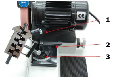
Loosen both head cap nuts (1+2) with a 10mm engineers wrench and remove the grinding wheel cover as shown on the picture.
Now open by use of an allen key SW 4.0, the screw in the center of the wheel support. Now you can remove the grinding wheel from the motor spindle. Open the grinding wheel support with the supplied key and change the grinding wheel.
When placing the support on the motor spindle, pay attention that the threaded pin is in the notch of the motor spindle (picture 3). Now fis the screw in the certer of the wheel support with the allen key SW 4,0 and mount the grinding wheel cover in the opposite sequence. Take care that the grinding wheel support is mounted correctly.
After the grinding wheel change make a 1 minute test turn. In case of uncommon performance, switch off the machine and check for cause of failure.

The ELITE B 20 is not allowed to be operated without correctly mounted grinding wheel cover!
7.4. Grinding of drills placing and adjustment of drills
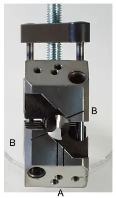
The reversing prism comprised a range of 2-20mm. The insertion and alignment of the drill is achieved in the most simple manner conceivable. Open the prism by means of the knurled head screw, provided for this purpose. Now insert the drill to be ground inside the prism.
Keep the drill projecting about 15-20mm beyond this prism edge. The prism jaws are pressed together by a slight turn of the knurled screw. The thus inserted drill is held tight in this position, but it can still be turned easily as this is important fo the alignment. Now it is only necessary to align the cutting edge of the drill in parallel to the two indicated marks (Mark A = right-hand drills; Mark B = left-hand drills)
The prism is to be tightened by hand only a hereafter, the grinding operation can be started.
Deviating from this basic adjustment, you can change your relief angle depending on the material to be drilled.
You want a higher clearance angle - a higher cutting capacity, then revolve the drill slightly to the left (shorter graduation mark on the prism). If you want less relief - a lower cutting capacity, then revolve the drill slightly to the right (longer graduation mark on the drill). You will thus obtain the correct cutting edge and angle for every kind of material.
In case of a broken drill, having no cutting edge for adjustment, grind the drill to get a truncated end. Align the cutting corners as closely as possible to the adjustment marks and regrind the drill until a new cutting edge appears. Thereafter the adjustment is to be carried out as before.
7.5. Adjustment of the top angle
In order to work always in conformity with the properties of the material, you have the opportunity to adjust every top angle that is possible.
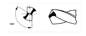
The common top angle are 118º, 130º and 180º degrees.
The angles are solidly marked on the prism slide. They can easily adjusted by opening the clamping lever (see section 5.3) and by moving the prism ret.
7.6. Grinding of the drills

Wear your safety glasses!
The prism, with the well aligned drill is slipped on to the prism swing pin and revolved in front of the grinding wheel. Simultaniously move the drill feed carriage towards the grinding wheel by means of the knurled nut until one side of the prism is well formed
Note the scale mark on the nut. Move backward the feed carriage by 2 to 3 scale marks closer to the grinding wheel.
The drill in this position is swiveled until no further formation of the sparks are visible.
In order to achieve the best possible cutting edge symmetry, the prism is reversed again by 180º without any alteration of the position of the drill feed carriage. The other siede is ground until no more spark are visible.

In order to prevent temper of anneal, please always work with low feeding grade.
7.7. Step drills
Grind the cutting edges of the first step same as standard twist drills. The cutting edges of the second step are likewise aligned in parallel with the indicated marks of adjustment (see section 7.4). The drill inside the prism is then pushed forward until the second step passes by the grinding wheel and touches the grinding wheel.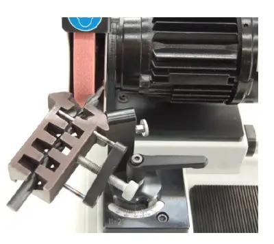
Using the knurled nuts 7 and 9 you can do the fine adjustment of the drill to the grinding wheel. Thereafter you resharpen the cutting edges by way of the reversal of the prism as described before for standard twist drills.
7.8 Sheet metal drills, wood drills, forstner drills and cutters
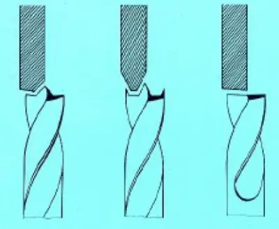
For the above mentioned drills it is recommended to use specially dressed grind wheel faces
Release the clamping lever of the prism rest and place on the adjustment line of the drill feed carriage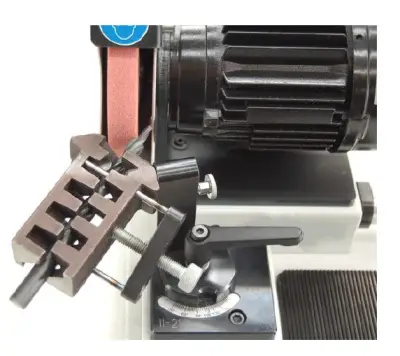
The adjustment of the drills is identical to twist drills. The fine adjustment of the drill to the grinding wheel is carried out with the screws (see section 5.3, num. 7 and 9)
By moving forward with the knurled nut, sharpen one cutter and after reversal of the prism, sharpen the second side (see section 5.3, num. 9). For milling cutters having 3 or 4 cutting edges you will need the magnetic depth stop. (optional).
Forstner drills in contrary to other drills are not adjusted according to adjustment marks on the prism, but aligned to the stagnant grinding wheel.
The grinding operation is same as for cutters.
Sharpening wood drill bits

7.9 Web thinning
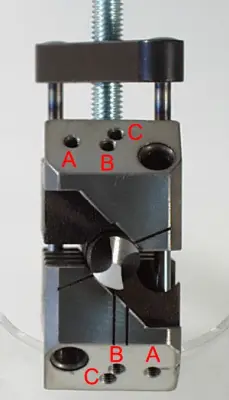
With the new clamping prism it is now possible to thin the web of the sharpened drill
- The boring holes A and B are for grinding of cutters and drills with 4 facet shape
- The bore C is for web thinning
For web thinning let project the drill 25mm outside the prism and do not change the position of the drill in the prism. Fix the prism with the knurled screw in hole C
Use the upper boring on the prism support. Loosen the clamping lever and move the prism support to 90º.
By use of the prism and motor feed, thin the web of the drill by using the left edge of the grinding wheel.
After one side is finished, note the graduation marks on the prism feed screw and move back for one turn. Now reverse the prism for 180º, fix again in hole C and move forward with the prism feed to the same graduation mark on the knurled screw.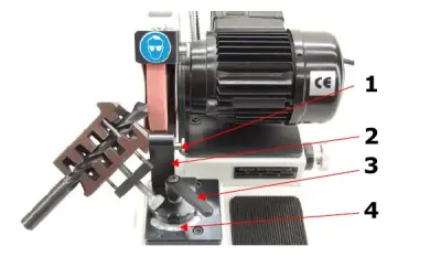
1.Fixation screw
2.Prism support
3.Clamping lever
4.90º
7.10 Cross or facet grinding
After the sharpening procedure, you have the possibility to change the standard twist drill shape to a cross or facet grinding.
The twist drill remains in the prism clamp without any changes in setting. Fix the prism with the fixation screw M4 in hole C (see section 7.9). Open the clamping lever and turn the prism support to 150º.
Move with the motor feed to the left, till you touch the cross cutting edge of the twist drill by the right edge of the grinding wheel.
Dive slowly into the center of the cross cutting edge by moving forward the prism feed. Notice the position on the feeding scale, move back, losen the fixation screw, reverse the prism for 180º. fix the screw again and move slowly forward again to the same position.
- Fixation screw M4
- Clamping lever
- 150º
8. SPARE PART LIST
| ITEM No. | Description |
|---|---|
| B 20-10 | Prism 2-20 mm |
| B 20-11 | Prism support |
| B 20-12 | Clamping lever M8 with washer for prism support |
| B 20-13 | Fixation screw for prism to prism support |
| B 20-14 | Pin 7 mm for prism support |
| B 20-15 | Dresser unit without diamond |
| B 20-16 | Spare diamond for dresser unit |
| B 20-17 | Scale-ring for the drill feed |
| B 20-18 | Scale-ring for the motor feed |
| B 20-19 | Grinding wheel cover, painted |
| B 20-20 | Motor 230 Volt / 50Hz, 2800 RPM; painted |
| B 20-21 | Cover for fan propeller |
| B 20-22 | Fan propeller |
| B 20-23 | Motor switch |
| B 20-24 | Box for motor switch without switch |
| B 20-25 | Grinding wheel support complete without grinding wheel |
9. MAINTENANCE
9.1.Preventive maintenance
The ELITE B20 drill grinder should be cleaned from grinding dust with a soft brush.
Persistent dirt, please clean with usual in trade machine cleaner. After cleaning, please grease all movable parts with some drops of machine oil.
To prevent erosion of the blank parts, also grease with little oil and rug with a soft rag.
Use the equipment only in dry environments. The temperature must be between 5 and 40ºC. Relative humidity greater than 90%, as well as a saline environment, would cause premature corrosion of the machine.
10.ACCESSORIES AND CONSUMABLES
10.1. Grinding wheels
For HSS steel drill bits we recommend using ELITE ref. nr. B20-4. Corundum ø125x20x20 mm
For HSS steel drill bits we recommend using ELITE ref. nr. B20-6. CBN grinding wheel ø125x20x20 mm
For tungsten carbide drill bits we recommend using ELITE ref. nr. B20-5. Diamond grinding wheel ø125x20x20 mm
11.WARRANTY
All our machines are tested before being shipped. However, there can always be defects that are not observable at first sight.
Our machines are guaranteed against manufacturing or material defects under normal use and maintenance conditions.
The period of this guarantee is 12 months from the date of purchase and consists of the replacement of defective material.
The guarantee will be automatically canceled in the event of a modification outside our company. Or in manifest cases of misuse of the machine.
The guarantee does not include parts subject to normal wear due to use such as skids, lubrication cartridge, abrasives, etc.
12.DOWNLOAD MANUAL
13.FAQ
Question nr1
Answer no. 1
